Enable VKS on VCF 9 – Supervisor Workflow
A few years ago, I wrote about the vSphere with Tanzu enablement workflow. With the introduction of VCF 9, the underlying architecture and the enablement workflow UI has undergone significant improvements. So here’s an attempt at documenting the new supervisor workflow as well.
Pro-Tip
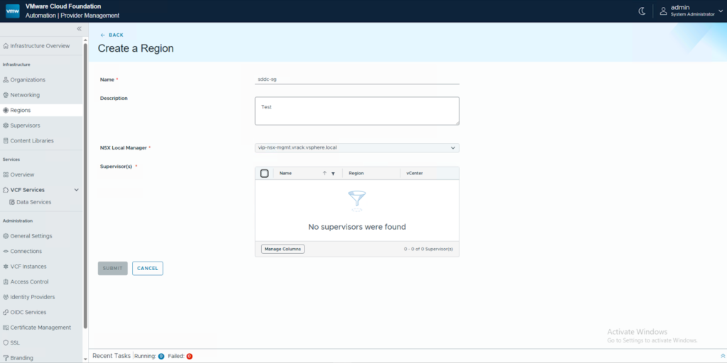
Enabling Supervisor Workflow is a pre-requisite to put your VCF-Automation to good use.
Pre-Requisites
(Optional) You can choose to use an existing content library and/or storage policy for the OVAs and VMs respectively.
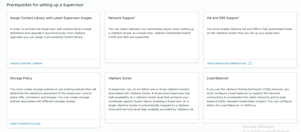
Network and Load Balancer Requirements
Choose one of the supported network options show below and prep the networks accordingly.
- VCF Networking with VPC
- NSX Classic (T0/T1/NSX Segments)
- vDS Networks (VLANs)
For the context of this blog we will use the VPC networking.
You will need to create an External IP Pool and a Private IP CIDR for the VPC you intend to deploy your Supervisor into. In my case, it will be the default VPC and hence I will update the Default connectivity profile to include these two CIDRs.
Based on the network stack you choose, your load balancing options might vary. For this blog, we will be using the in-built NSX Load Balancers.
Supervisor Management Workflow
- Login to the vCenter and Navigate to the Supervisor Management page. Click on Get Started.

- Choose the networking stack and continue.

- Setup a vSphere zone or choose cluster-based deployment.

- Enter the name of the supervisor for your cluster-based deployment.

- Choose the control plane storage policy for your Supervisor Control Plane VMs to be placed in.

- Specify the Management Network details to be used for your Supervisor VMs. In my case, I will be using a DHCP based network and hence the fields are empty.

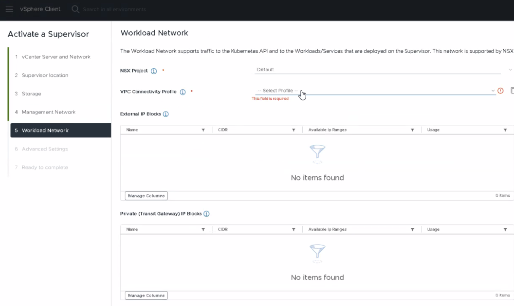
- In the Workload Network section, NSX Project and VPC Connectivity Profile dropdown’s should have been auto-populated by now. If not, then please follow the KB to rectify your T0/outbound NAT configuration.

- Change the control plane sizing settings and specify a FQDN to be used by the Control plane API, if desired.


- And voila, that’s it. You have enabled VKS on VCF with VPC.

- Once the installation is complete, you should see a screen similar to the one below and the IP assigned to the Control Plane should be from the External IP pool that you specified. You can point this IP to the FQDN you specified in step 8.

Lessons Learnt
You should consider yourself lucky, if you are able to complete the installation without any troubleshooting. Well, I wasn’t. Could be because I performed this installation on a nested lab. But also, I wasn’t paying attention to the details. So to not let you suffer the way I did, here are a few lessons I learnt by doing.
T0 Misconfiguration
When I got to the workload network configuration, the VPC Connectivity Profile dropdown was empty. You will be unable to proceed with the installation since it’s a mandatory field. This happens because you haven’t either enabled outbound traffic on your VPC connectivity profile or your T0 is Active/Active. You can follow this KB to rectify this and move forward.
vSAN Alarms
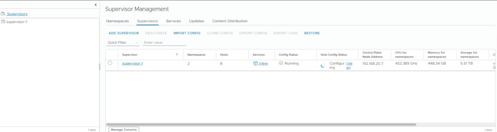
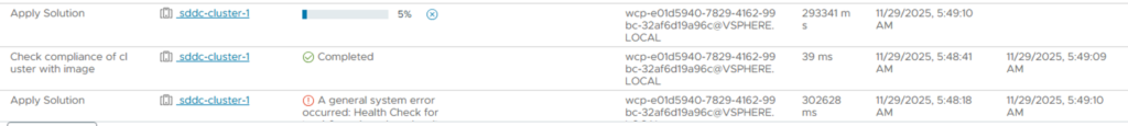
Okay, this one might be specific to nested environments. But, there might be occurrences of this in a real-world scenario as well. Once the installation was kicked off, I had errors pointing to Host Configuration setup not being able to complete.
Now, when I navigate to the cluster object and look for alarms, I couldn’t find anything alarming. However, if you look at the vSAN Health, you should see something like the one’s below.
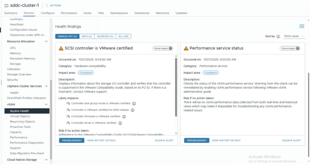
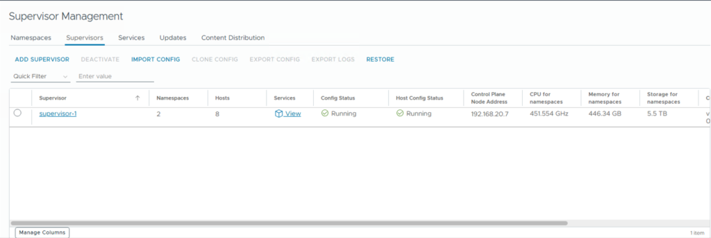
I chose the easier thing to do 🙂 I silenced these alerts. But you know what’s the right thing to do. Once the right thing is done, you should now see everything up and running.
And, that’s about it for this article. I will cover how to use VCF-A to deploy your VKS clusters in the following series of articles. Until then, happy learning!